Product encyclopedia
Flue gas dampers reduce heat loss and increase the operational safety of the fireplace
| The applications | Motorized flue gas damper | Thermal flue gas damper |
|---|---|---|
| Atmospheric gas fireplace | + | + |
| Floor standing boiler and wall unit | + | + |
| Boiler with forced draught burner | + | |
| Solid fuel fireplace | + | |
| Biomass boiler | + | |
| Tiled stove, chimey stove, open fire | + | |
| Single stove, gas stove | + | |
| Gas stoves with chimney operation | + | |
| Combustion air duct for fireplaces | + | |
| Fireplaces on air-flue-gas system | + |
Introduction
The European Union’s Green Paper estimates that about 20% of the population suffers from sound problems that cause sleep disturbance, annoyance and health problems. Among the many sources of noise, such as traffic, aircraft, construction sites, noise sources in the house are not very common, but all the more intrusive. One of the sources of noise can be the heating system. We have summarized for you here how sound affects us and when sound is perceived as annoying.
What is sound?
Sound can be defined as a pressure variation that is perceptible to the human ear. As with a stone thrown into water, wave motions are created here in the air that spread out from the sound source. Sound propagates through the air at about 1,200 km/h. The range that can be perceived by the human ear depends on the frequency and the sound pressure level. The normal hearing of a healthy young person can perceive a frequency from 20 Hz to 20,000 Hz (20 kHz) and a sound pressure level from 0 dB to the pain threshold of 130 dB and above.
The sound and the hearing
 Compared to static air pressure, audible sound pressure variations are very small and range from about 20 µPa, which corresponds to the hearing threshold in normal hearing, to 100 Pa, which is perceived as painful.
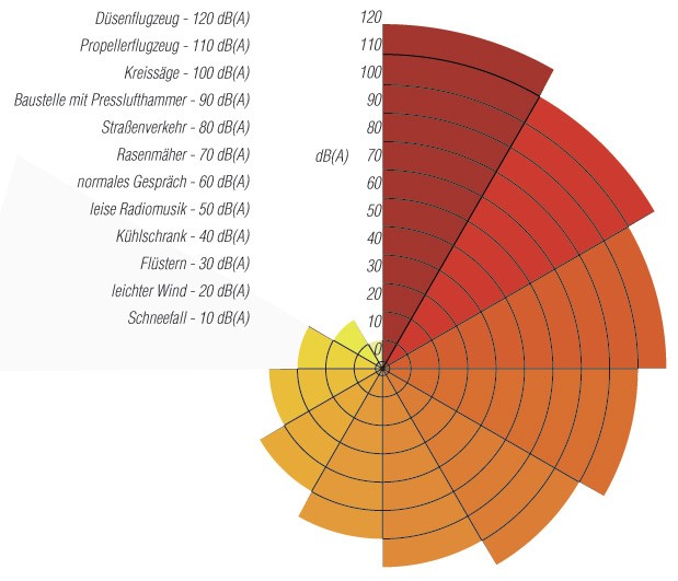
The ratio of these two extreme values is more than one million to one. However, the ear does not hear in physical exactness, but perceives a ten times higher sound pressure approximately twice as loud. Therefore, sound pressures are reproduced logarithmically.
This logarithmic ratio is then called decibel (abbreviation dB). The figure clearly shows the advantage of this application: The scale starts at 0 dB(A) at the limit of audibility and ends at 130 dB (A) at the pain threshold.
Our hearing is also less sensitive at very low and high frequencies. To take this into account, weighting filters can be applied to the sound measurement. The most common frequency weighting currently used is A-weighting, with results often referred to as dB(A), which roughly corresponds to the sensitivity of the human ear.
Sound propagation
How loud is a heater? Many different factors influence the sound pressure level. To explain this, we need to look at sound radiation from the source, sound propagation in the air, and the impingement of sound waves on walls and ceilings.
The main factors are:
- Sound source type: Heaters and chimneys are sound point sources. With them, the sound energy propagates spherically, so that the sound pressure level is the same at all points at the same distance from the sound source.
- Distance from the sound source: That is, the distance from the heater or chimney from which the sound emanates. For point sources, the sound pressure level decreases by 6 dB per doubling of distance.
- Obstacles such as walls or buildings: When sound waves hit a surface, some of their acoustic energy is reflected, some passes through, and some is absorbed. When absorption and transmission are low (generally true of buildings), most of the sound energy is reflected and the surface is said to be acoustically hard. Accordingly, the sound pressure level near the surface comes from directly radiated sound as well as single or multiple reflected sound.
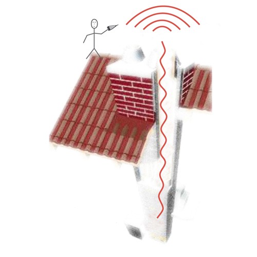
Propagation of exhaust noise from heating systems
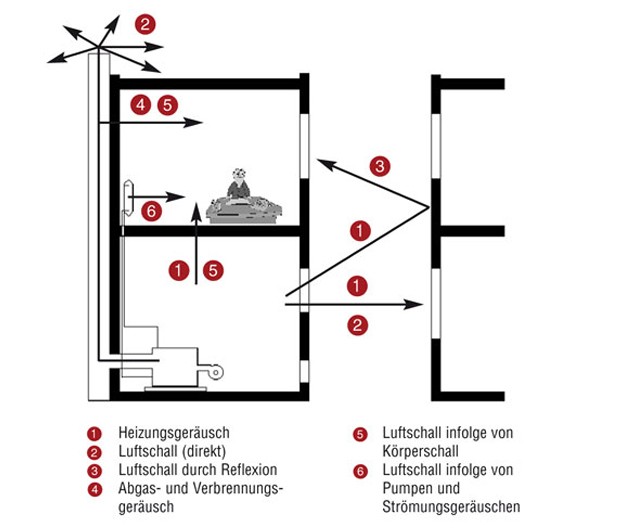 A fundamental distinction must be made between the noise in the installation room (see diagram below) and the noise that is transported via the flue gas system. These two sound levels have different propagation criteria and must not be confused with each other under any circumstances. For example, a sound level of 60 dB (A) can be measured next to the boiler in the installation room, but in the flue gas system the values are much higher, perhaps 90 dB (A).
In other words, a quiet installation room does not mean that the noise in the flue gas path is also tolerable.
Limits for noise
The assessment of noise from heating systems in the neighborhood is carried out according to “TA Lärm”.
Among other things, immission guide values for immission points outside buildings (0.5 m in front of the open window of rooms requiring protection) are specified there.
They vary depending on the type of use of the construction area.
Table – Immission guide values according to “TA Lärm” for places of immission outside buildings (A-weighted)
| In industrial areas | during the day | 70 dB(A) |
| at night | 70 dB(A) | |
| In commercial areas | during the day | 65 dB(A) |
| at night | 50 dB(A) | |
| In core areas, village areas and mixed areas | during the day | 60 dB(A) |
| at night | 45 dB(A) | |
| In general residential areas and small residential areas | during the day | 55 dB(A) |
| at night | 40 dB(A) | |
| In pure residential areas | during the day | 50 dB(A) |
| at night | 35 dB(A) | |
| In spa areas, for hospitals and nursing homes | during the day | 45 dB(A) |
| at night | 35 dB(A) |
The DIN 4109 standard regulates the permissible A-weighted sound pressure level in rooms requiring protection in third-party residential areas.
Table – Permissible A-weighted sound pressure levels of heating systems at night in rooms requiring protection
| Living rooms and bedrooms Classrooms and workrooms | during the day | 35 dB(A) |
| at night | 25 dB(A) |
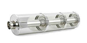
Reasons for flue gas silencer
Airborne and structure-borne noise is generated during the operation of a fireplace. These are transmitted from the installation room via the floor, ceilings and walls into the neighboring rooms and via the exhaust system and shafts also into other rooms and into the open air.
The result can be noise nuisance in adjacent apartments and even at the neighbor’s due to exhaust noise from the mouth of the exhaust system. Therefore, cooperation between the architect, the building owner and the planner/specialist engineer as well as the creator of the heating system is recommended already in the planning phase.
In modern heating systems, low frequencies predominate, although some peculiarities of sound propagation or transmission between the heat generator and the mouth must be taken into account. They can cause individual narrow-band sounds (tones) to stand out clearly and be particularly disturbing even at a greater distance in the building or its surroundings. With an flue gas silencer in the connecting piece, the transmission of this noise into the flue gas system and thus onto the building and into the open air is effectively reduced.
What is fine dust?
 Fine dust consists of tiny particles less than one-hundredth of a millimeter in diameter, or about one-tenth the diameter of a human hair, or PM10, which is less than 10 micrometers (µm) in size. Soot particles are even smaller with PM2.5, these are released, among other things, during the combustion of wood. Fine dust damages the respiratory tract and causes cardiopulmonary diseases. The particles with the small size of PM2.5 penetrate deep into the lungs and can cause lasting damage. The Federal Environment Agency provides information on its own website on Fine dust emissions of the size PM2.5. In regions with high levels of fine dust, there also appears to be a higher risk of covid 19 disease and severe courses are more likely.
Exceeding the limits
The European Union has set limits for air pollution control in the EU for the smaller PM2.5 fine dusts, among others, and has established an assessment and control system for this purpose.
Legal regulations for the reduction of emissions
An EU directive on air quality and cleaner air for Europe was transposed into German law with the Federal Immission Control Ordinance.
Why silencers?
So that you and your customers feel good!
The noise level is continuously increasing due to more and more people in the same space. For an environment in which people feel comfortable, the manufacturers of household appliances and heat generators are committed to ever quieter appliances. These devices are muffled in their noise output by the silencers.
In conjunction with increasingly dense building envelopes and double-glazed windows, noise can be reduced to a comfortable level even in large cities.
To ensure that modern boiler systems do not disturb this tranquility, many OEM partners rely directly on Kutzner + Weber products. However, we also solve your situational noise nuisance after the fact. With our products, you too can meet the environmental requirements according to TA-Lärm DIN 4109 and VDI guideline 2715.
Causes of noise generation and their influence – Burner and combustion noises
The causes of noise described in the following section are, in principle, approximately the same for oil and gas furnaces.
a) Fan noises:
Flow noise is usually a major contributor to heating noise in forced-air burners. Additional noise may be generated by throttling devices and by motor or blower imbalance, bearing or blade damage.
b) Start-up noises:
When starting up the heating system, for example, unfavorable matching between the burner and boiler can result in up to 10 dB higher A-weighted sound pressure levels of the combustion noise compared to continuous operation, due to the sudden volume expansion of the combustion and flue gas.
c) Combustion noises:
- Aerodynamic noise generated by turbulent flow processes during the mixing of combustion air and fuel. The noise component has largely equal sound pressure levels over a wide frequency range.
- Flame noise as a result of the small explosive volume changes occurring during the combustion reaction, in which predominantly low frequencies are level-determining.
- Flame-excited cavity vibrations generated by the reaction of pressure fluctuations in the boiler/flue gas system on the flame and characterized by low-frequency tones.
d) Structure-borne sound:
Structure-borne sound is generated by mechanical vibrations of the heat generation system and is transmitted in solid bodies, i.e. foundations, walls, floors as well as in the walls of the flue gas system. It is converted into airborne sound by radiation from the boundary surfaces and is thus audible.
The noise level of cogeneration units is about 50 – 60 dB(A), which is about as loud as a washing machine. Decoupling via rubber mats to the floor and rubber lines to the pipes results in less noise. However, it is not the CHP unit itself that is more problematic, but the flue gas pipe in which a pressure vibration is generated. It’s very difficult to decouple them.
A combined heat and power plant (CHP) is a modular system for generating electrical power and heat, which is preferably operated at the site of heat consumption or feeds useful heat into a local heating network.
Common CHP modules have electrical outputs between five kilowatts and five megawatts. Internal combustion engines, i.e. diesel or gas engines, but also gas turbines can be used to drive the generator.
Below 15 kW they are also called small cogeneration units and are used to supply individual buildings. The flue gas noise generated by engine operation often cannot be sufficiently reduced by conventional absorption silencers.
This is due to the fact that low-frequency (humming) sounds are authoritative. Often the highest sound levels are found at 63 or 80 Hz.
The following silencers are suitable for noise reduction in oil or gas-fired forced draught boilers:
- Silencers specially designed for the interfering frequencies
- Optimum sound attenuation already from 50 Hz
- Attenuates single frequencies up to 30 dB
- Reduction of the sum level by up to 25 dB(A) possible
- In combination with passive silencers broadband attenuation
- Particularly suitable for boilers, combined heat and power units and internal combustion engines
- Best attenuation at high frequencies between 1000 and 2000 Hz
- Hardly any attenuation at low frequencies (80 to 250 Hz)
- Steady increase of the attenuation power towards high frequencies
Passive silencer NW 50 mm
- suitable for oil and gas fuels
- Suitable for condensing operation
Passive silencer NW 80 mm
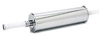
- suitable for installation in plastic pipes DN 80 mm
- with lip seal
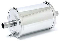
Even with modern oil and gas boilers that operate with fan assistance, noise can be perceived as annoying in the building or in the neighborhood due to transmission via the jlue gas system.
Especially at low frequencies in the range of 125 to 500 Hz, the sound levels are at their highest.
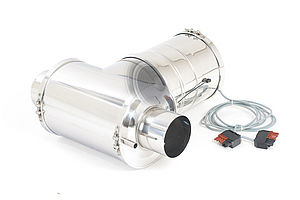
Special attention in the development of boilers is increasingly paid to the fact that the devices require little space in the installation room.
To then integrate an flue gas silencer in these small devices, which reduces low frequencies, can be realized with the following silencer.
Realizable with the following silencer:
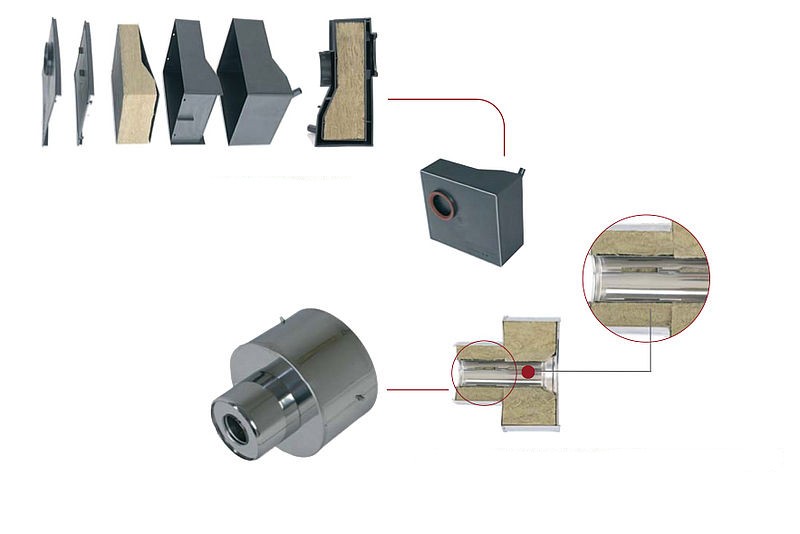
- Dimensions and geometry to customer requirements
- Silencing in the smallest space
- Particularly suitable for installation in boilers
- Great design ability in shape and dimension
- Very tough construction
- Proven in serial operation
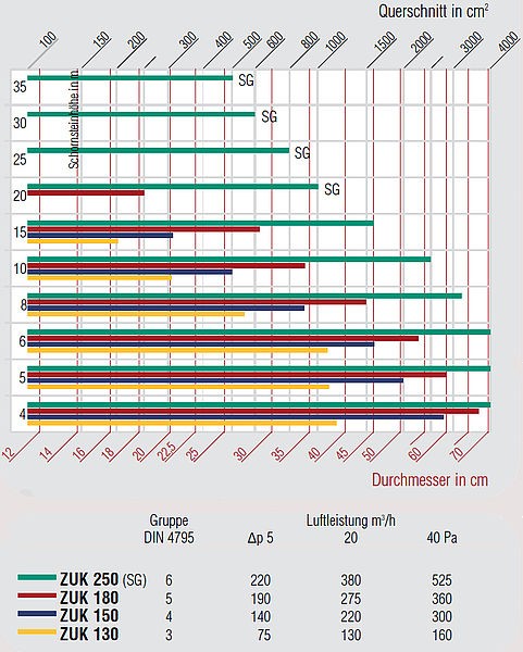
In recent years, Kutzner + Weber has received a large number of sound measurements from the responsible sound measurement partners or carried them out itself.
The following diagram provides a tendency statement about the noise level of oil or gas fan boilers at the chimney outlet or the outlet of an lue gas system.
For this purpose, more than 300 sound measurements could be evaluated and assigned to the various boiler outputs.
However, individual installations may well be turned up. The low-frequency hum of oil and gas forced-air burners usually occurs between 125 to 500 Hz.
Please note:
The curves shown in the diagram can only serve as reference values. The sound pressure levels of an flue gas system depend on a wide variety of factors.
For example, the burner and boiler design, the materials used, the diameter and height of the flue gas system and, last but not least, the number of baffles present all influence the existing sound level.
The safest way is the specific design of flue gas silencers after the commissioning of the boiler.
If this is not possible, at least sufficient space for the subsequent installation of silencers should be planned from the outset!
VDI guideline 2715 must also be observed!
 Airborne and structure-borne noise is generated during the operation of a fireplace. These are also transmitted outdoors and can be measured there.
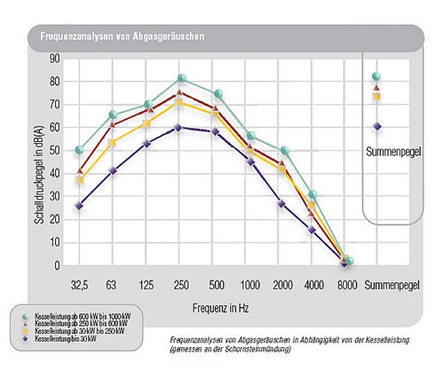
Table – Frequency analyses of exhaust gas noise as a function of boiler output
The following silencers are suitable for noise reduction in oil or gas-fired forced draught boilers:
- Silencers specially designed for the interfering frequencies
- Optimum sound attenuation already from 50 Hz
- Attenuates single frequencies up to 30 dB
- Reduction of the sum level by up to 25 dB(A) possible
- In combination with passive silencers broadband attenuation
- Particularly suitable for boilers, combined heat and power units and internal combustion engines
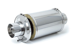
The Active+ Silencers
- Assembly in the tightest space
- Attenuates low frequencies from 125 Hz
- Almost halves the noise
- Insertion loss according to DIN EN ISO 7235 available and can be requested
- Best attenuation at high frequencies between 1000 and 2000 Hz
- Hardly any attenuation at low frequencies (80 to 250 Hz)
- Steady increase of the attenuation power towards high frequencies
Draught regulators improve the efficiency of fireplaces
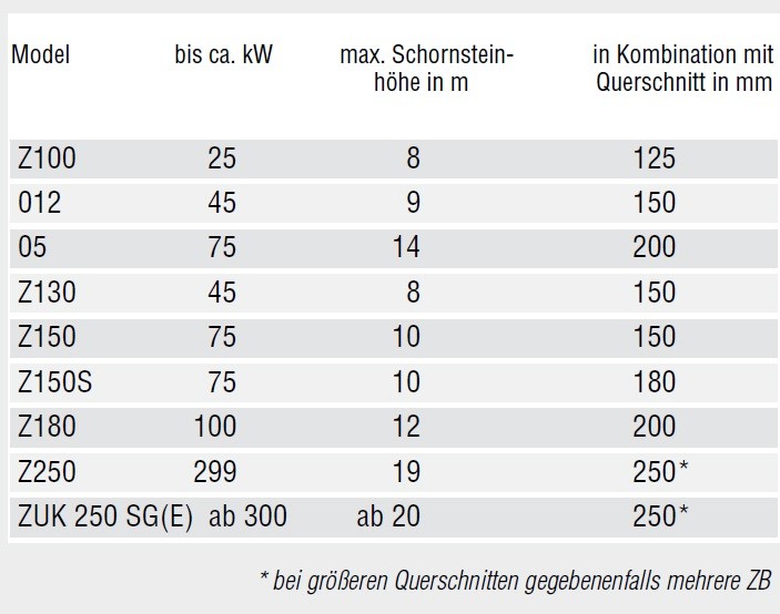
Model selection based on our experience
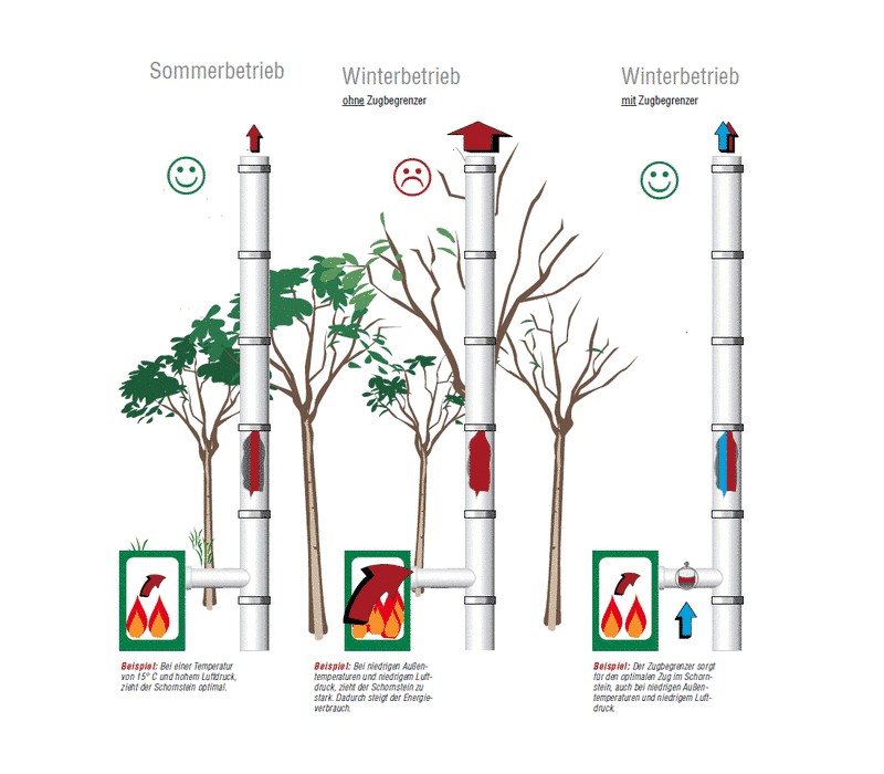
The performance of a flue gas system is subject to natural fluctuations due to weather conditions and temperature differences between seasons. Draught regulators, also referred to as secondary air devices in DIN 4795, are mechanical or motorized components that create uniform negative pressure conditions in a flue gas system.
To ensure safe operation, flue gas systems are designed for an assumed outside temperature of 15 °C (according to EN 13384). During the heating period, when the systems are mainly operated, the temperature gradient may cause excessive negative pressure in the system. This fans the combustion in an uneconomical way, worsening the efficiency and increasing the energy consumption. Draught regulators limit the negative pressure to the optimum value for the fireplace.
As soon as the draught in the chimney exceeds the optimum value, the damper of the draught regulator opens and limits the negative pressure to the optimum value for the fireplace via the additional air volume supplied. When the preset value is reached, the damper closes again. This process, as simple as it is effective, ensures uniform combustion and measurable energy savings.
Draught regulators increase the efficiency of single fireplaces by 20% and extend the burning time by 40%.
Draught regulator selection overview
Draught regulators have a positive effect on the chimney draught (negative pressure in the flue gas section) and combustion values in every respect. The result of a study by the Fraunhofer Institute for Building Physics (IBP) confirms significantly lower emissions, better efficiency and consequently lower operating costs.
The efficiency of the devices was proven in a study by the Fraunhofer Institute for Building Physics (IBP). The result is impressive: a nearly 40% longer burning time with the same amount of fuel, a reduction in chimney draught of almost 75% and an almost 20% increase in combustion efficiency combined with corresponding cost savings and reduced pollutant emissions.
Due to the savings in fuel costs, the device pays for itself in a short time, depending on the use of the fireplace. Kutzner + Weber Draught regulators conform to DIN 4795 standards.
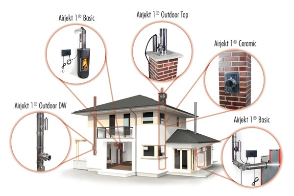
The Draught regulators from Kutzner + Weber can be installed both indoors and outdoors
Reasons for secondary air devices
Modern fireplaces place particularly high demands on the flue gas system. A standard-compliant secondary air device offers the possibility of adapting the chimney to the fireplace regardless of the mode of operation.
You optimize the energy balance and the emission output of your heating system.
The installation of a secondary air devices causes:
- Compensation of weather-related vacuum increases
- Lowering of the dew point and thus later condensate failure